Options Menu
The CAM section (computer-aided manufacturing) shows all the settings related to robot manufacturing operations, such asrobot machiningor 3D printing, and how to import robot toolpaths created using CAM software.
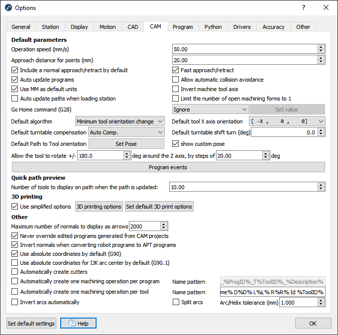
TheOperation speedis the default speed used in operations for curve and point follow projects. The curve/point follow project is available in theUtilitiesmenu.
TheApproach distance for pointsis the default distance used to approach to points in a point follow project. This option is useful for applications like drilling or spot welding.
Include a normal approach/retract by defaultwill include a 100 mm normal approach to the toolpath.
It is possible to ignore theGo Home command(G28 ISO code) set by some robot machining programs or set it to a specific value (XYZ coordinates).
TheProgram eventsdefines what actions are taken for specific G-code events, such as setting digital outputs, managing extruder heads or triggering specific programs at different stages of the manufacturing operation.
Other options are available to define the default settings when a new robot machining project is started. These are the same settings available from therobot machiningmenu.
TheQuick path previewsection allows setting how many tools are displayed as a preview when moving the reference frame or the tool frame of a manufacturing operation.
It is possible to open the3D printing optionsof the Slicer from the 3D printing section. A Slicer splits an object into a machine toolpath, then, the toolpath can be easily converted to a robot program with RoboDK.
机器人程序从CAM生成程序modified after they have been generated. However, updating the settings from the robot machining menu will override any previously generated program. CheckNever override edited programs generated from CAM projectsto avoid losing any changes.
TheLength of the displayed path normals (mm)is the length of the white vector representing the normal of the CAM toolpath. The CAM toolpath is displayed in green.