Robot Calibration (Optical CMM)
A RoboDK station is where the virtual environment station and calibration information is stored. The station is saved as an RDK file. Follow the next steps to create a robot station for robot calibration from scratch (video preview:https://youtu.be/Nkb9uDamFb4):
1.Select the robot:
a.SelectFile➔Open online library. The online library will show up in RoboDK.
b.Use the filters to find your robot by brand, payload, ...
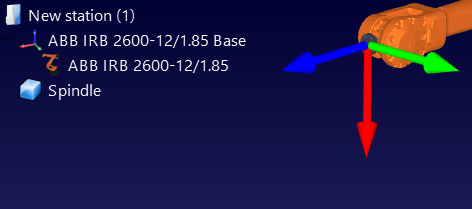
c.Select2022世界杯国家队名单and the robot should automatically appear in the station.
d.Alternatively, download the robot files (.robot file extension) separately from//m.sinclairbody.com/libraryand open them with RoboDK.

2.Model the virtual station
a.Add reference frames by selectingProgram➔Add Reference Frame.
i.One “Measurements reference” frame must be added with respect to the robot base frame.
ii.One “Tracker reference” must be added with respect to the “Measurements reference” that we just added.
iii.One additional “Tool reference” can be added with respect to the “Measurements reference” frame to visualize the position of the tool seen by the tracker.
Tip 1:Drag and drop items in the tree to reconstruct the dependency that exists in the real world. For example, the tracker reference must be placed with respect to the “Measurements Reference”.
Tip 2:你可以约移动任何参考系or tool frames by holding the ALT key and SHIFT+ALT key respectively. Alternatively, you can double click the reference frame and input the right coordinates.
Tip 3: Rename any object using the F2 key on the item tree.
b.Add the tool object (STL, IGES and STEP files are supported formats) and drag and drop it to the robot (inside the item tree), this will convert the object into a tool. More information availablehere.
 ➔
➔
Optional: SelectProgram➔添加空工具to add any TCP’s that we want to visualize in the station (to check for collisions or other). To set an approximate value of the TCP:
i.Double click the new tool.
ii.Set an approximate TCP value. You can copy/paste the 6 values at once using the two buttons at the right.
iii.It is recommended to rename the TCPs used for calibration with the name “CalibTool id”, where id is the calibration target number.

c.Add other 3D CAD files (STL, IGES, STEP, SLD, ...) to model the virtual station using the menuFile➔Open…Alternatively, drag and drop files to RoboDK’s main window.
Tip 1: Import the 3D files of the measurement workspace and name it Workspace so that the robot measurements are generated inside the workspace of the tracker. Alternatively, set the workspace invisible if we do not want to constrain the measurements inside the tracker workspace. More information is available in the next section.
Tip 2: It is possible to select CTRL+ALT+Shift+P to block exporting confidential 3D files that have been imported in RoboDK.
3.Add the calibration module in the station:
a.Select the menuUtilities➔Calibrate Robot.
b.SelectStereo camera.

Then, the following window will appear.

This window can be closed for now. We can open it anytime by double clicking theRobot calibrationstation item.

4.Save the station.
a.SelectFile➔Save station.
b.Provide a folder and a file name.
c.Select save. A new RDK file will be generated (RoboDK station file).
We can recover the station modifications anytime by opening the RDK file (double click the file on Windows).
Summarizing, it is important to double check the following points:
1.The reference frame “Measurements reference” is directly attached to the robot base reference frame.
For now, we can use an estimate of this reference frame (approximate value).
2.TheTracker referenceis directly attached to theMeasurements reference. The tracker reference must be an estimated position of the tracker measurement device with respect to the measurements reference.
3.The “Robot calibration” project is present in the station and all the measurements that we are planning to take are free of collision and visible by the tracker (double click the calibration settings and select show for each group of the four group of measurements).
4.If we want to automatically check for collisions we must use the name tag “collision” in every object that we want to use to check collisions. It is recommended to use a tool around 25% bigger than the calibrated tool to safely avoid collisions.