Mold Machining
This example will help you create a simple 3 axis machining project in RoboDK using the Mastercam plugin. In this example a Motoman robot with a cutting tool is simulated and programmed to machine a simple mold using the robot as a 3-axis machine. You will learn how to transform a CNC program into a robot simulation and a robot program.
With the RoboDK plug-in for Mastercam you can quickly set up robot machining projects direclty from Mastercam to RoboDK. This plug-in allows you to program more than 50 different robot manufacturers and 500 robots directly from Mastercam.
The RoboDK plug-in for Mastercam supports NCI (native preprocessed Mastercam files) and standard APT CLS and G-code files. The plug-in is free if you have purchased a RoboDK license.
To start the project, you will first have to select RoboDK’s 3-axis mold machining example in the default library.
下面的例子使用了Motoman GP180 robot, a cutting tool mounted on a spindle and a table to hold the part in place.
Load the station:
1.SelectFile➔![]() Open
Open
2.Locate the3-axis mold machining examplefromRoboDK’s examples section:
C:/RoboDK/Examples/Plugin-Mastercam-3-Axis-Mold-Machining.rdk.
Now that you have loaded the station you can open Mastercam and load the project fromC:/RoboDK/Other/Plugin-Mastercam/Examples/Mold.mcam.
Open your 3D object in Mastercam and launch the cutting simulation. In this example, the 3D object is a mold metal piece with an already created cutting path using Mastercam tools.
To simplify this example, the number of passes required to machine that part has been greatly reduced. In reality, you would have a lot more lines or cutting path in the mold that you wouldn’t be able to really see the tool in action.

The Mastercam cutting simulation shows you every movement the tool needs to do during the program.
Follow the next steps to load your part into RoboDK:
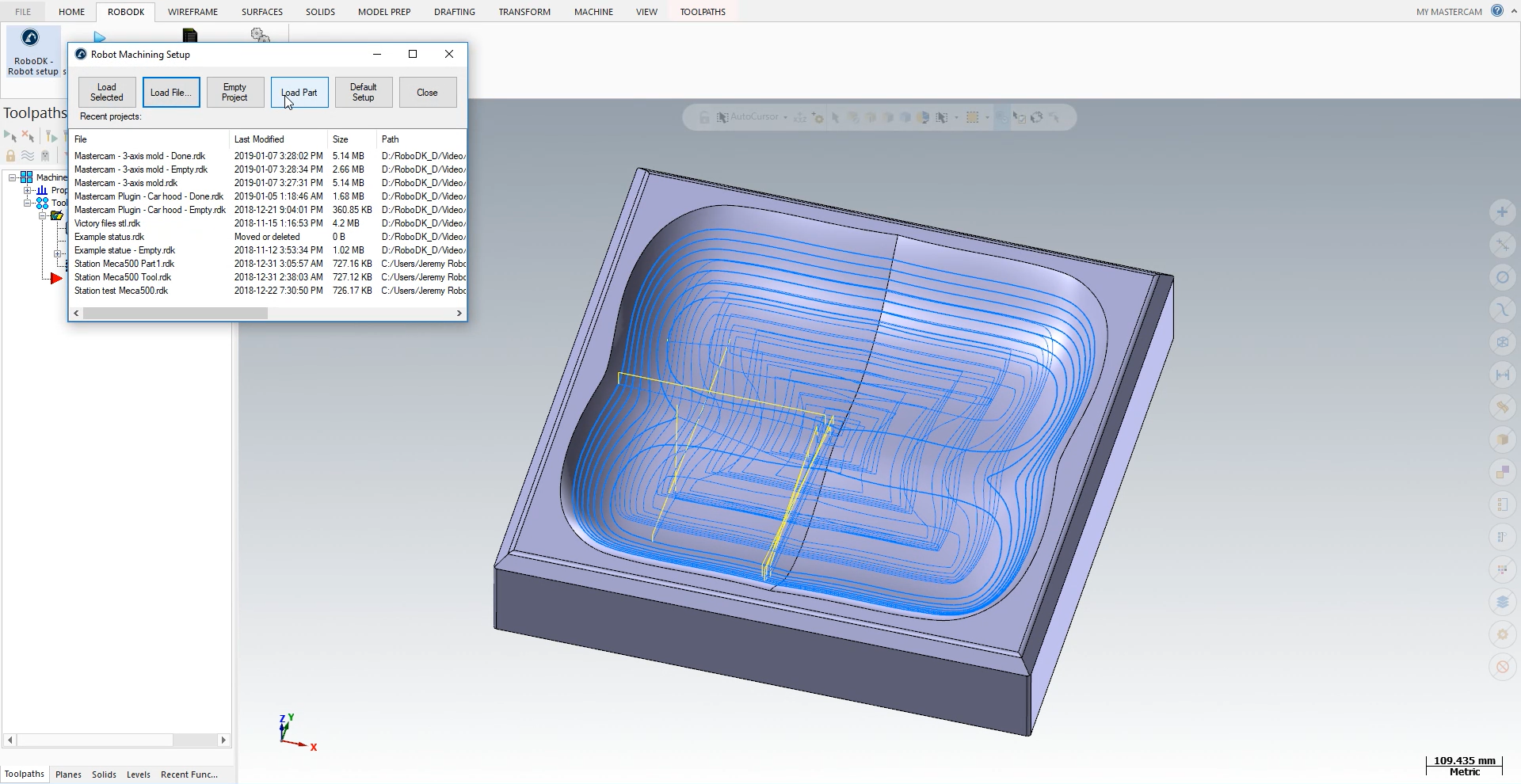
1.Select the RoboDK tab and selectRoboDK – Robot setup.
2.SelectLoad Part.
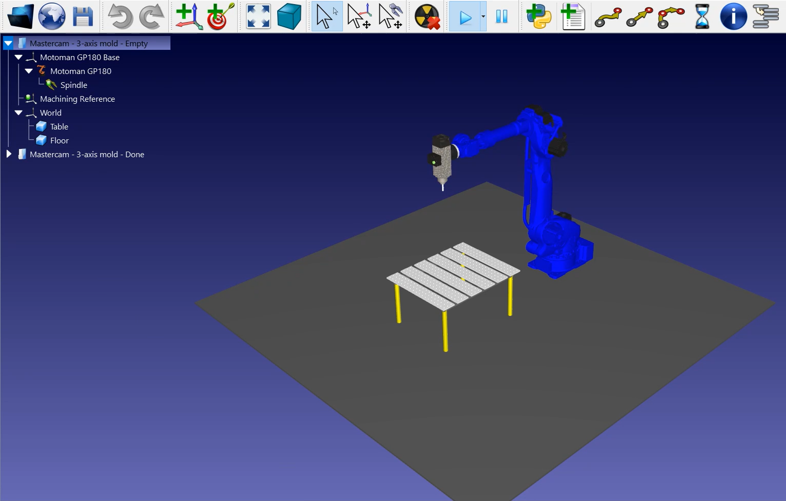
You should see thepartloaded on the active reference frame (Machining Reference) on the table of the RoboDK station.
The next step is to import the cutting path from Mastercam to RoboDK.
1.Select theRoboDKtab in Mastercam.
2.SelectRoboDK – Update selected operations.
3.Go to RoboDK.
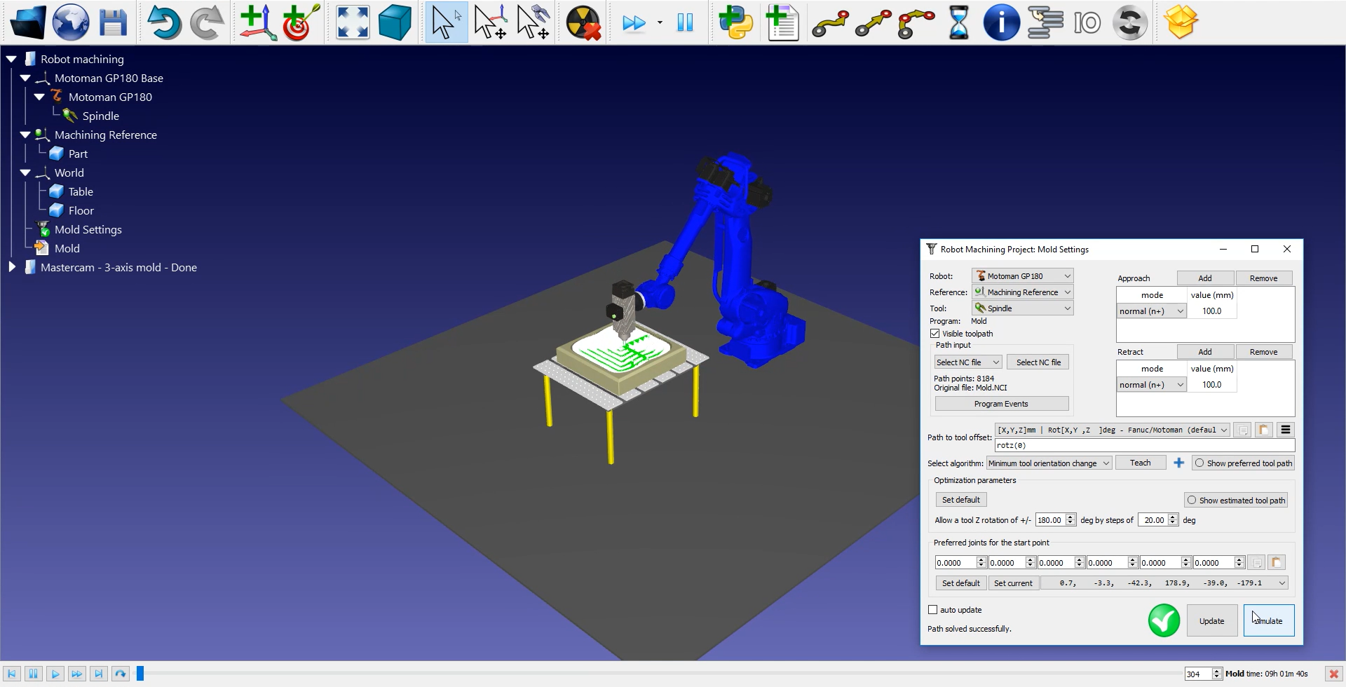
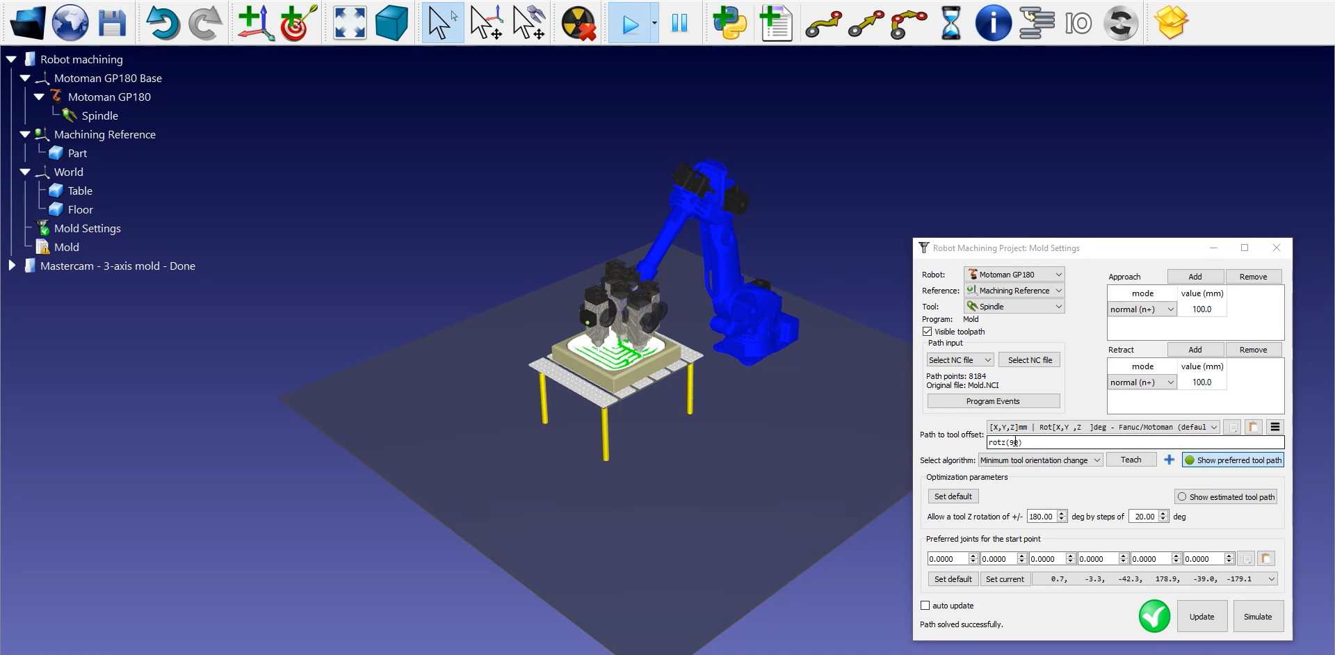
Once the robot machining path has been imported in RoboDK you should see the robot machining toolpath attached to the mold reference of your RoboDK station.In![]() Mold Settings, make sure that you select the correct robot, reference frame and tool.
Mold Settings, make sure that you select the correct robot, reference frame and tool.
You can also adjust the value of the approach and retract movements before and after the cutting path. A 100 mm should be fine in this example. If there is a risk of collisions, you can increase those as much as you want inside the robot working range.
下一步就是验证顺序the path sections will be executed is correct by selecting![]() Mold Settings➔Update➔Simulate. In this example it is not necessary to readjust the order.
Mold Settings➔Update➔Simulate. In this example it is not necessary to readjust the order.
Follow these steps to adjust the tool orientation:
1.Double click on the![]() Mold Settings.
Mold Settings.
2.SelectShow preferred tool path. Some ghost tools will appear as shown in the image below. Those represent the position of your tool along the path.
3.Modify therotz (0)value by scrolling your wheel up until90 degrees. You will see the rotz value changing and the ghost tolls position changing with it.
4.SelectUpdate➔Simulate.
To generate your robot program, make sure to use the right post processor. Double click on the![]() MotomanGP180robot and click onSelect Post Processor➔Motoman.
MotomanGP180robot and click onSelect Post Processor➔Motoman.
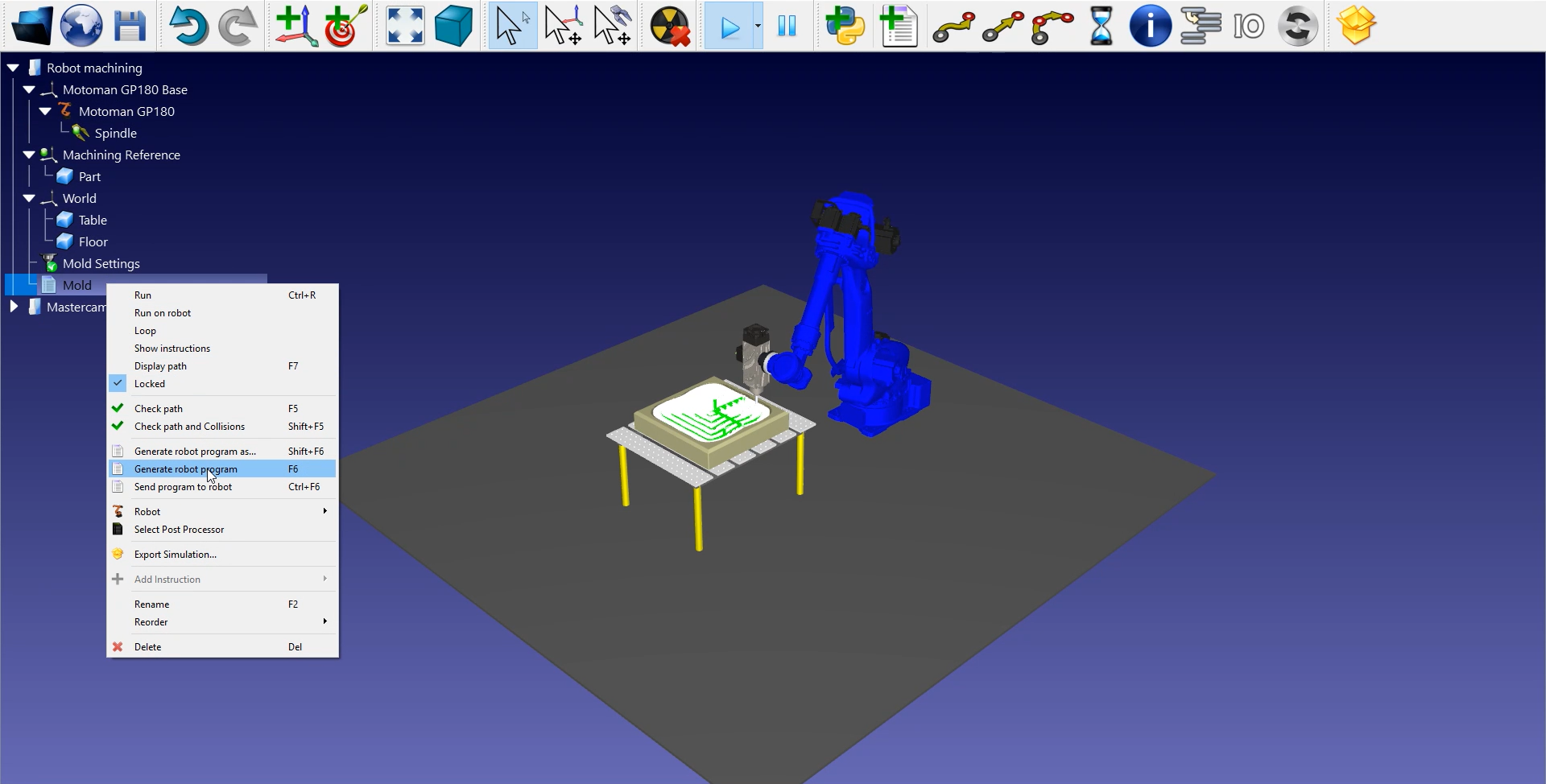
Finally, right click on![]() Mold➔Generate robotprogram or pressF6.
Mold➔Generate robotprogram or pressF6.
The Motoman JBI file is now ready to be transferred to your robot controller.