机器人工具或工具中心点(TCP),是point used to move the robot to a Cartesian position (such as a Cartesian target given XYZWPR values). The TCP is defined as a transformation from the robot flange. Defining the TCP properly is important in any robot application, either if it involves Offline Programming or not.
Follow these steps to define or calibrate a robot tool (Tool Center Point, or TCP):
1.SelectUtilities➔Define Tool Frame (TCP)
2.Select the Tool to define/calibrate. Alternatively, right click a tool and selectDefine TCP.
3.Select the method:
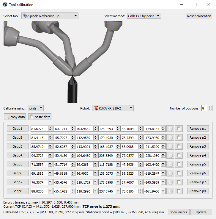
a.Touching a point with the tip of the TCP, using different tool orientations (Calib XYZ by point)
b.与TCP触摸一架飞机,使用不同的l orientations (Calib XYZ by plane). The TCP can be a point or a sphere.
Note:Touching the same point using different orientations (first method) is the same method most robot controllers have available on the teach pendant. Use RoboDK to get a better idea of the TCP errors.
Note:If the center of a sphere needs to be calculated it is recommended to use a plane to define the TCP. This method automatically retrieves the center of the touch probe.
4.TCP calibration using joint values is the default setting. Change it to poses if you have the Cartesian targets.
Important:If the TCP is defined using poses, the position of the robot flange must be provided as a pose (position and orientation), with respect to the robot base or a reference frame. More information on how to provide these values in theReference Framessection.
Tip:It is possible to use more than 3 or 4 configurations to properly define or calibrate the TCP. This allows obtaining a more accurate result and provides a good estimate of the TCP error. It is recommended to use 8 points or more to define a TCP accurately, or 3 points if accuracy is not important.
5.Select the robot if more than one robot is available in your project.
6.Adjust the number of points that you would like to use to calibrate the TCP. This value can also be modified later.
7.Start filling the table with the measured configurations (joint values or position and orientation of the flange).
8.Finally, selectUpdateto apply the new position tool selected in the RoboDK Station.
Video:This video shows how you can properly calibrate your robot tool (TCP) using an Omron TM robot: https://www.youtube.com/watch?v=TM-9vGR2r4k&list=PLjiA6TvRACQd8Zju_r_VSL7LBNEmBE57E&index=2.
Tip:The list of configurations can be filled manually or by using the copy/paste buttons (on the right of each line).
Important:It is recommended to provide each joint value with at least 4 decimals (when providing joint values). The allowed number of decimal values can be changed in Tools➔Options➔Accuracy➔Max Decimals.
Tip:It is also possible to selectGet p1to get the current joint values from the real robot to RoboDK. If the robot driver has properly been set up you can easily obtain this position on the PC. More information available in theRobot DriversSection.
Important:It is recommended to keep a separate copy of the values being provided. SelectCopy dataandPaste datato copy/paste all the contents.
Note:The new tool (TCP) is calculated automatically once the values have been entered.
Tip:Some useful error statistics are provided as the mean error, standard deviation (std) and maximum error. SelectShow errorsto display a graphic with the errors for each point against the calculated average. Since this method involves a lot of manual operations it is common to introduce errors in specific points. To isolate these errors, we can iteratively delete the points that shows a larger error compared to the average.
As an example, the following image shows the errors before point 6 was deleted by selecting theRemove p6button.